
Efficient and Quality Air Conditioning for Your Home. Episode 1 - The MVHR Solution
Abstract
Most households accept a frustrating compromise: ventilate the home and lose the heat you paid for, or seal the building and breathe progressively stale air. Mechanical Ventilation with Heat Recovery (MVHR) resolves this trade-off at the intersection of thermodynamics, air quality engineering, and embedded control systems. This is case study is the first in a series of posts that walks through the problem in full, and explains how an MVHR unit addresses it. In this episode, I catalogue the physical components involved and review the embedded software design: a requirements-led control specification, an operating mode state machine, and a practical super loop architecture that demonstrates for an initial design one do not particularly need a real-time operating system to achieve deterministic, reliable control of a domestic HVAC system. In a follow up episode, we discuss some of the more practical considerations.
Table of Contents
- The Problem: Fresh Air Versus Retained Heat
- The MVHR Solution
- System Components
- Operating Modes
- System Overview
- Embedded Control Design
- The Super Loop Architecture
- Scalability and Production Considerations
- Conclusion
- References
1. The Problem: Fresh Air Versus Retained Heat
A well-insulated modern home is, by design, nearly airtight. Building regulations across the UK, Europe, and North America have progressively tightened envelope requirements in pursuit of lower heating bills and carbon targets [2]. The result is a building that holds heat well but cannot breathe.
The consequences accumulate quietly. Carbon dioxide levels rise as occupants exhale, causing the cognitive blunting and fatigue that many people attribute to other causes. Volatile organic compounds (VOCs) from cleaning products, cooking, furniture, and adhesives build up without dilution. Humidity from showers, cooking, and respiration condenses on cold surfaces, seeding mould and degrading building fabric. In short, the same envelope that saves energy also degrades air quality and occupant health when ventilation is absent.
The traditional remedy is to open a window. This works but wastes the energy already spent heating or cooling the room. In a well-insulated home where the heating bill has been carefully minimised, opening a window to ventilate can account for a significant fraction of total heat loss. The more airtight the building, the worse this trade-off becomes.
Intermittent extract fans in bathrooms and kitchens address localised moisture and odour problems but do nothing for background CO2 levels in bedrooms or living rooms, and they create negative pressure that draws cold unfiltered air through gaps in the building fabric rather than through any controlled pathway [1].
What is needed is a system that can move fresh air in and stale air out continuously, without discarding the thermal energy carried by the exhaust stream. That is precisely what MVHR delivers.
2. The MVHR Solution
Mechanical Ventilation with Heat Recovery is a whole-house ventilation strategy in which a central unit simultaneously extracts stale air from wet rooms (bathrooms, kitchens, utility rooms) and supplies fresh air to habitable rooms (bedrooms, living rooms, studies), recovering up to 90 percent of the heat from the exhaust stream before it is discharged outdoors [3].
The physics is straightforward. The extract and supply airstreams pass on opposite sides of a highly conductive heat exchanger matrix. They do not mix, but heat transfers from the warm extract side to the cold supply side. In winter, cold incoming air arrives at the living spaces pre-warmed. In summer, a bypass damper can divert the supply air around the exchanger entirely, allowing cooler night air to flush the building without picking up heat from the warmer indoor exhaust stream.
A well-specified and commissioned MVHR system delivers several simultaneous benefits. Heating energy demand falls because incoming ventilation air arrives close to room temperature. Air quality improves because ventilation is continuous rather than intermittent, keeping CO2 and VOC levels low around the clock. Humidity is managed because the extract stream carries moisture out of the building before it can condense. Noise from external traffic is attenuated because windows can remain closed. And filtration on the supply side removes pollen and particulates, which is meaningful for allergy sufferers [4].
3. System Components
An MVHR installation comprises four distinct layers of components. Understanding them separately is essential before designing the control system, since the controller must address each layer.
3.1 Air Handling
- Supply fan (EC motor): draws fresh air in from outdoors and pushes it to habitable rooms.
- Extract fan (EC motor): draws stale air from wet rooms and exhausts it outdoors.
- Heat exchanger: transfers heat between airstreams without mixing them.
- Bypass damper: diverts supply air around the exchanger in summer cooling mode.
3.2 Filtration
- Outdoor intake filter (G4 / F7): removes insects, dust, and pollen from supply air.
- Extract filter (G4): protects the exchanger from indoor lint and dust.
- Carbon / NOx filter (optional): useful in urban installations with high outdoor pollution.
3.3 Sensing
- Supply temperature: measures air delivered to rooms and supports comfort monitoring and heat recovery efficiency.
- Extract temperature: measures air leaving rooms and supports heat recovery calculation and mode logic.
- Outdoor temperature: measures external ambient conditions and supports frost protection and bypass enable logic.
- Humidity (extract): measures indoor moisture load and supports boost mode and condensation prevention.
- CO2 (extract): measures occupancy and metabolic load and supports demand-controlled ventilation and boost triggering.
- VOC (extract): measures cooking, cleaning, and off-gassing activity and supports boost triggering and air quality indexing.
- Differential pressure: measures filter loading and supports filter change alerts and maintenance scheduling.
3.4 Actuation
- Supply fan motor: controlled by PWM, 0-10V, or Modbus RTU for variable speed and primary airflow control.
- Extract fan motor: controlled by PWM, 0-10V, or Modbus RTU for balanced, independent speed control.
- Bypass damper: controlled by 0-10V proportional or 3-point signalling to open or close the bypass path.
- Pre-heater (optional): controlled by on/off or PWM to prevent frost damage in deep cold conditions.
Representative components meeting these roles include electronically commutated fan motors [10] and proportional damper actuators [11], both readily available with the analogue or digital control interfaces listed above. On the sensing side, the CO2 and VOC channels are commonly served by NDIR and metal-oxide gas sensor modules respectively [8] [9].
4. Operating Modes
Before writing a line of control code, it is essential to enumerate the distinct operating modes the system must support. Each mode represents a combination of sensor conditions that demands a specific actuator response. Leaving a mode undefined at the design stage guarantees discovering it unexpectedly in production.
- NORMAL: all sensors remain within bounds and no special condition is active; the fans run at the demand setpoint and the damper stays closed.
- BOOST: CO2, VOC, or humidity exceeds its threshold; both fans move to maximum speed and the damper remains closed.
- BYPASS: outdoor temperature is warmer than indoor temperature and the warm-season flag is active; the fans run at demand speed and the damper opens.
- FROST PROTECT: outdoor temperature falls below the frost threshold; the supply fan is reduced and the pre-heater is enabled if fitted.
- FAULT: a sensor failure, fan failure, or watchdog expiry is detected; the fans move to a safe minimum or off and the damper remains closed and latched.
The priority ordering of mode evaluation matters. Frost protection must override a concurrent boost demand: no amount of elevated CO2 justifies drawing freezing air across an unprotected heat exchanger at full fan speed. Fault detection must be evaluated before mode logic so that a sensor failure does not result in an undefined actuator command.
5. System Overview
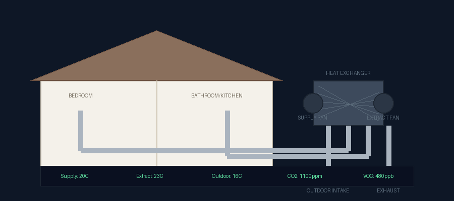
Figure 1: MVHR system showing supply and extract airflow paths, heat exchanger, fans, and sensor monitoring points.
The diagram above illustrates the physical layout of a typical residential MVHR installation. Fresh outdoor air enters at the base right, passes up through the supply fan and through the heat exchanger where it is warmed by the outgoing extract stream, then travels horizontally through the supply duct to the bedroom supply vent. Stale air is drawn from the bathroom and kitchen extract vent, travels through the extract duct to the extract fan and through the opposite side of the heat exchanger, and exits at the base left as cooled exhaust.
The dashboard at the bottom of the diagram represents the controller readout: supply temperature, extract temperature, outdoor temperature, CO2 concentration, and VOC level. These five values are the primary inputs to the embedded control algorithm described in the following section.
5.1 Animated HMI
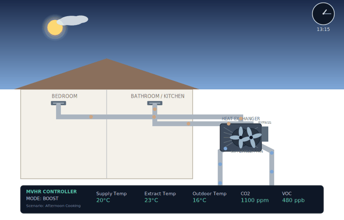
Figure 2: SVG-based animated HMI showing the Afternoon Cooking (BOOST) scenario. Fan rotation speed, airflow particle velocity, and dashboard values all reflect current controller state.
The SVG-based HMI shown above was designed to serve simultaneously as a marketing simulation, an embedded display panel, and a web-based monitoring interface. Each animated element is bound to a named DOM ID, allowing the controller or a connected MQTT subscriber to update sensor values and fan speeds with a single JavaScript property assignment. The day and night sky, cloud movement, and analogue clock, driven natively by SVG’s SMIL animation facilities [18], allow the system to contextualise its operating state temporally: a cold night with the moon visible and the clock reading 02:30 immediately communicates why the system is in FROST PROTECT mode without requiring the user to interpret numerical outputs.
6. Embedded Control Design
The control system for an MVHR unit is a classic embedded supervisory controller: it reads a set of physical inputs on a periodic schedule, evaluates them against thresholds and logical conditions, selects an operating mode, and issues actuator commands accordingly. The sensor update rates involved (CO2 changes on a timescale of seconds, temperature on a timescale of minutes) place no hard real-time demands on the processor. A well-structured super loop is therefore not a compromise; it is the architecturally appropriate solution.
6.1 Control Requirements
Derived from the component analysis, the embedded controller must satisfy six functional requirements in every execution cycle:
- Read all sensors on a defined schedule, tolerating temporary communication failures without entering a fault state.
- Evaluate air quality, temperature differentials, and filter condition against configurable thresholds.
- Select one operating mode from the priority-ordered mode hierarchy.
- Issue actuator commands consistent with the selected mode.
- Report current status to any connected display or network interface.
- Persist fault history and filter runtime to non-volatile memory at a defined interval.
6.2 Communication Architecture
Practical Engineering considerations for the communication architecture is fully fleshed in future posts. For now, a generic Field-level communication between the controller and sensors or actuators emphasises the need to consider distances greater than one metre calls for a robust, differential, multi-drop bus. RS-485 [7] running Modbus RTU [5] satisfies all requirements since it operates reliably over distances up to 1200 metres on a single twisted pair, and is immune to the ground potential differences encountered between a loft-mounted unit and a bathroom sensor on a lower floor, and is the native interface presented by most commercial HVAC sensors and EC fan motors.
Tier 2 communication, carrying telemetry and commands to a supervisory system, a cloud broker, or an HMI, uses MQTT [17] with the Sparkplug B payload specification [6]. Sparkplug B adds birth and death certificates, metric naming conventions, and state management to standard MQTT, making it directly interoperable with industrial SCADA platforms while remaining lightweight enough for a microcontroller MQTT client. Sparkplug B encodes its DDATA payloads using Protocol Buffers, for which nanopb provides a suitable embedded-target implementation [15]. The Sparkplug namespace for this system takes the following form:
spBv1.0/MVHR/NBIRTH/EON-01
spBv1.0/MVHR/DDATA/EON-01/sensors
spBv1.0/MVHR/DDATA/EON-01/fans
spBv1.0/MVHR/DDATA/EON-01/controller
7. The Super Loop Architecture
A real-time operating system earns its complexity when a system has tasks with hard sub-millisecond deadlines, genuinely concurrent independent processes, or dynamic workloads requiring preemptive scheduling [13]. None of these conditions apply to an MVHR controller. Its workload is periodic, sequential, and composed entirely of soft-deadline tasks operating on sensor inputs that change on a timescale of seconds.
The correct architecture is therefore a super loop: a single infinite loop that executes a fixed sequence of operations on every tick, with a hardware timer setting the tick period. The approach offers determinism by construction, trivial worst-case execution time analysis, no mutex or priority inversion concerns, and a significantly simpler certification path if the product is ever submitted for safety assessment.
The one genuine challenge for a super loop in this application is Modbus RTU inter-frame timing. The Modbus specification requires 3.5 character-times of bus silence between frames. At common baud rates, this is in the range of 0.3 to 4 milliseconds. The solution is to handle all Modbus framing in a hardware UART with DMA, of the kind found on microcontroller platforms such as the RP2040 [12]: the silicon manages byte timing and frame boundaries autonomously, depositing complete frames into a buffer that the super loop reads on each tick. The loop never waits for the bus; it simply checks whether a new frame has arrived.
Similarly, the MQTT client must operate in non-blocking mode. The loop stuffs outgoing Sparkplug payloads into a circular transmit queue; a lightweight non-blocking send call drains one packet per tick. The WiFi or Ethernet stack interrupts handle the transport layer independently.
7.1 Sensor Shadow Pattern
Because Modbus polling is distributed across many loop ticks (one device polled per tick, rotating around the device list), not all sensor values are fresh on every tick. The sensor shadow pattern resolves this cleanly. The controller maintains a struct of the last known value for every sensor, indexed by device address. Each completed Modbus read updates one entry. The evaluate and actuate stages always read from this shadow: they never block waiting for a bus transaction. The shadow value for any given sensor is stale by at most one full poll cycle, which for air quality and temperature measurements is entirely acceptable.
7.2 Super Loop Pseudocode
INIT:
  initialise UART DMA, Modbus, PWM, NVM
  load filter_runtime, fault_log from NVM
  set fans to safe minimum speed
  mode = NORMAL

LOOP (target tick: 100ms):

  // Step 1: Service UART DMA buffer
  if modbus_frame_complete:
    parse frame -> update sensor_shadow[device_address]

  // Step 2: Issue next Modbus request (round-robin)
  device_index = (device_index + 1) mod NUM_DEVICES
  send_modbus_request(device_index)

  // Step 3: Evaluate (reads from shadow, never blocks)
  if outdoor_temp < FROST_THRESHOLD:    mode = FROST_PROTECT
  elif fan_fault or sensor_stale:       mode = FAULT
  elif co2 > CO2_HIGH
    or voc > VOC_HIGH
    or rh  > RH_HIGH:                  mode = BOOST
  elif outdoor_temp > indoor_temp
    and warm_season:                    mode = BYPASS
  else:                                 mode = NORMAL

  if filter_dp > FILTER_LIMIT: raise filter_change_flag

  // Step 4: Actuate
  switch mode:
    NORMAL:        fans = demand_speed;  damper = CLOSED
    BOOST:         fans = max_speed;     damper = CLOSED
    BYPASS:        fans = demand_speed;  damper = OPEN
    FROST_PROTECT: supply_fan = reduced; pre_heater = ON
    FAULT:         fans = safe_minimum;  damper = CLOSED; latch

  // Step 5: Report (non-blocking)
  update HMI display fields
  enqueue Sparkplug DDATA payload
  mqtt_service_send_queue()   // drains one packet, non-blocking

  // Step 6: Persist (gated by interval)
  if persist_timer_elapsed:
    write filter_runtime, fault_log to NVM

  // Step 7: Watchdog and sleep
  pet_hardware_watchdog()
  sleep_until_next_tick()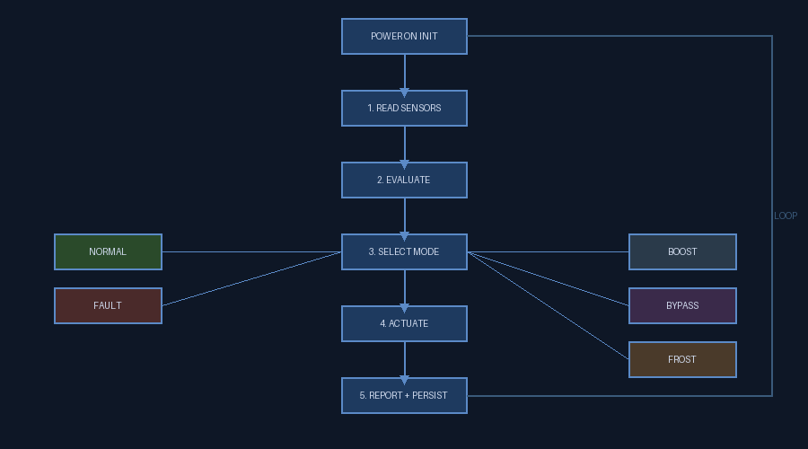
Figure 3: Super loop execution flow showing the seven-step cycle with mode selection branching. All execution paths return to the loop head on every tick.
The loop period of 100 milliseconds is conservative for this application. At 9600 baud Modbus, one complete request-response cycle takes approximately 10 to 20 milliseconds depending on device response time. Polling eight devices therefore completes one full round-robin in under two seconds, which is well within the acceptable update rate for all sensor types deployed. The tick period can be tuned without modifying any control logic: it is a single constant at the top of the firmware.
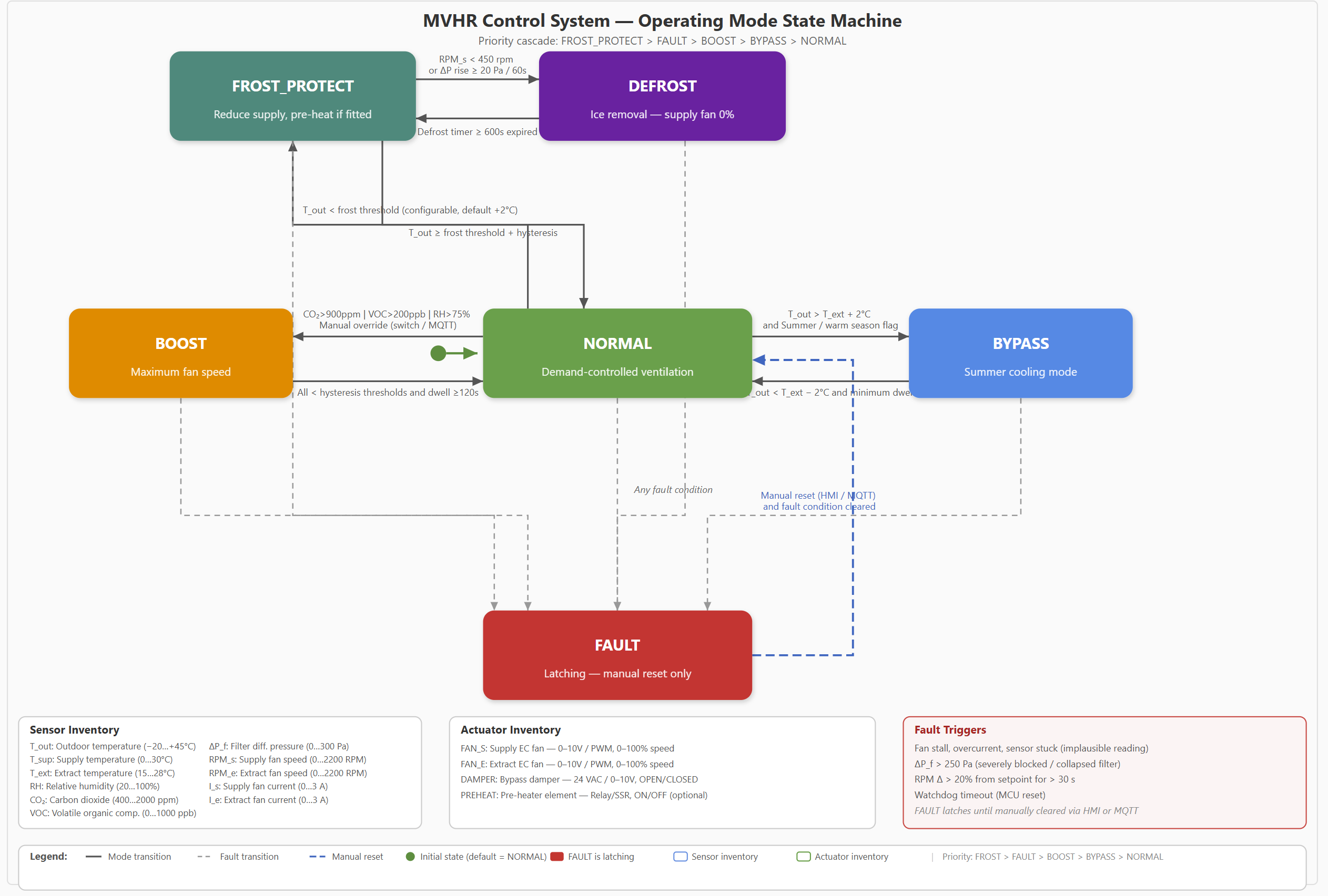
Figure 4: MVHR operating mode state machine showing transitions between modes with priority ordering: FROST_PROTECT > FAULT > BOOST > BYPASS > NORMAL.
8. Scalability and Production Considerations
The architecture described here is intentionally minimal, targeting a single residential MVHR unit. Several extensions are straightforward within the same framework.
Multi-zone installations add additional Modbus devices to the poll list and additional entries to the sensor shadow struct. The loop structure does not change. Zone-specific boost or bypass logic is added as additional conditional branches in the evaluate step.
Remote monitoring and fleet management are addressed entirely at the Tier 2 layer. The controller publishes Sparkplug DDATA topics on every tick; a cloud-hosted MQTT broker aggregates data from multiple units, optionally via a gateway tier built on an embedded Linux BSP [14]. The HMI SVG subscribes over MQTT WebSockets and receives live updates without polling.
Filter lifetime management uses the NVM-persisted filter runtime counter incremented each tick. When the counter exceeds a configurable threshold, the filter change flag is raised in the dashboard and published as a Sparkplug metric. No hardware change is required to implement predictive maintenance.
Safety certification, should the product be developed commercially, benefits directly from the super loop architecture and can draw on established functional-safety guidance for electrical and programmable systems [16]. The absence of dynamic memory allocation, task scheduling, and preemption makes the control flow statically analysable. A Modbus watchdog (sensor considered stale if no successful read within N consecutive ticks) and a hardware watchdog timer (resets the controller if the loop stalls) provide the primary safety mechanisms.
9. Conclusion
MVHR represents one of the most effective interventions available to improve both the energy performance and the indoor air quality of a modern home. The physics is well understood, the components are commercially mature, and the embedded control problem is well-scoped: a handful of sensors, two variable-speed motor actuators, a damper, and a state machine with five modes.
The case study presented here demonstrates that this control problem does not require an operating system, a complex communication stack, or exotic hardware. A deterministic super loop with DMA-backed UART, a sensor shadow pattern, and a non-blocking MQTT client provides reliable, auditable, and maintainable control within the timing constraints of the application.
The SVG-based HMI developed alongside this case study illustrates how the same sensor data that drives actuator decisions can simultaneously feed a visually rich human interface, bindable to any web-capable display or embedded screen. The gap between industrial embedded control and accessible user experience is narrower than it appears.
References
[1] CIBSE Guide B2: Ventilation and Ductwork. https://www.cibse.org/knowledge/knowledge-items/detail?id=a0q20000008I7PXAA0
[2] Building Regulations Approved Document F: Ventilation (UK 2021 edition). https://www.gov.uk/government/publications/ventilation-approved-document-f
[3] Passivhaus Institut: Mechanical Ventilation with Heat Recovery. https://passipedia.org/planning/building_services/ventilation/heat_recovery_ventilation
[4] Good Homes Alliance: MVHR Best Practice Guide. https://goodhomes.org.uk/resources/mvhr
[5] Modbus Application Protocol Specification v1.1b3. https://modbus.org/docs/Modbus_Application_Protocol_V1_1b3.pdf
[6] Eclipse Sparkplug B Specification v3.0. https://www.eclipse.org/tahu/spec/sparkplug_b_specification.pdf
[7] RS-485 Application Note: TI SLLA036. https://www.ti.com/lit/an/slla036/slla036.pdf
[8] Senseair S8 CO2 Sensor: OEM Reference Manual. https://rmtplusstoragesenseair.blob.core.windows.net/docs/publicerat/PSP107%20-%20S8%20OEM%20Modbus%20comm%20guide.pdf
[9] Sensirion SGP41 VOC and NOx Sensor Datasheet. https://sensirion.com/media/documents/5FE8673C/61E96F50/Sensirion_Gas_Sensors_Datasheet_SGP41.pdf
[10] ebm-papst EC Fan Technology Overview. https://www.ebmpapst.com/topics/ec-technology.html
[11] Belimo Actuator Technical Documentation: LM24A-SR. https://www.belimo.com/mam/general-files/technical_documentation/Belimo_LM24A-SR_Data-Sheet_EN.pdf
[12] Raspberry Pi RP2040 Datasheet: PIO State Machines. https://datasheets.raspberrypi.com/rp2040/rp2040-datasheet.pdf
[13] PREEMPT_RT Real-Time Linux Wiki. https://wiki.linuxfoundation.org/realtime/start
[14] Yocto Project Documentation: meta-raspberrypi BSP Layer. https://meta-raspberrypi.readthedocs.io
[15] nanopb: Protocol Buffers for Embedded Systems. https://jpa.kapsi.fi/nanopb/
[16] IEC 61508: Functional Safety of E/E/PE Safety-related Systems (overview). https://www.iec.ch/functional-safety
[17] MQTT Version 5.0 OASIS Standard. https://docs.oasis-open.org/mqtt/mqtt/v5.0/mqtt-v5.0.html
[18] W3C SVG 2 Specification: SMIL Animation. https://www.w3.org/TR/SVG2/
Glossary
CO2 (Carbon Dioxide): The gas whose extract-side concentration this controller monitors as a proxy for occupancy and metabolic load, triggering BOOST mode when it exceeds threshold.
DMA (Direct Memory Access): The peripheral capability that lets the UART deposit complete Modbus frames into memory autonomously, so the super loop never blocks waiting on bus timing.
EC motor (Electronically Commutated motor): The variable-speed motor type used for both the supply and extract fans, allowing the controller to command precise airflow at each operating mode’s setpoint.
G4 / F7: EN779 filter grade codes used for the intake and extract filters in this system; G4 is a coarse dust filter, F7 a finer pollen-capable filter, with the choice driven by desired supply-air cleanliness.
HMI (Human-Machine Interface): The SVG-based animated dashboard described in Section 5.1, bound to controller state so fan speed, temperatures, and mode are visible to an operator without reading raw sensor values.
Modbus RTU: The serial protocol running over RS-485 in this design, used for field-level communication between the controller and its sensors and EC fan motors.
MQTT (Message Queuing Telemetry Transport): The lightweight publish-subscribe protocol used at Tier 2 to carry telemetry and commands between the controller and a supervisory system or cloud broker, here wrapped in the Sparkplug B payload convention.
MVHR (Mechanical Ventilation with Heat Recovery): The whole-house ventilation strategy that is the subject of this post, extracting stale air and supplying fresh air while recovering heat between the two streams.
NOx (Nitrogen Oxides): A pollutant class targeted by the optional carbon/NOx filter stage in urban installations with elevated outdoor air pollution.
NVM (Non-Volatile Memory): The persistent storage this controller writes filter runtime and fault history to at a defined interval, so that state survives a power cycle.
PWM (Pulse-Width Modulation): One of the control signal options for driving the fan motors and pre-heater, alongside 0-10V analogue and Modbus RTU digital control.
RS-485: The differential, multi-drop serial bus standard used for field-level Modbus RTU communication in this design, chosen for its long reach and immunity to ground potential differences between a loft-mounted unit and a lower-floor sensor.
SCADA (Supervisory Control and Data Acquisition): The class of industrial monitoring platform that Sparkplug B’s birth/death certificates and metric conventions make this controller’s telemetry directly interoperable with.
Sensor shadow: The pattern, described in Section 7.1, of maintaining a struct holding the last known value for every sensor, so the evaluate and actuate stages always read fresh-enough data without blocking on a bus transaction.
SMIL (Synchronized Multimedia Integration Language): The SVG animation standard referenced for the day/night sky and clock elements in the HMI, allowing time-based visual state without a JavaScript animation loop.
Sparkplug B: The MQTT payload specification layered on top of standard MQTT in this design, adding birth and death certificates and metric naming so the controller’s telemetry is directly interoperable with industrial SCADA platforms.
Super loop: The single infinite loop architecture, described in Section 7, that executes a fixed sequence of read, evaluate, actuate, report, and persist steps on every tick, chosen here in place of an RTOS because the workload has no hard sub-millisecond deadlines.
UART (Universal Asynchronous Receiver/Transmitter): The hardware peripheral that, paired with DMA, manages Modbus byte timing and frame boundaries independently of the super loop.
VOC (Volatile Organic Compound): The class of off-gassed chemicals from cleaning products, cooking, and furnishings that this controller monitors on the extract side as a BOOST trigger alongside CO2 and humidity.